pH Adjustment - A Primer -
A brief review of the definition of pH, the pH
scale, and some of the chemistry involved in pH Adjustment systems
is provided below. For some this may be trivial, yet for many others
this may be useful. The information provided below is typical of the
background information we provide in our training classes and
seminars.
By definition pH is the measure of free hydrogen
activity in water and can be expressed as:
pH= -log[H+]
In more practical terms (although not technically correct in all cases) pH is the measure of free acidity or free alkalinity of water. Measured on a scale of 0-14, solutions with a pH of less than 7.0 are acids while solutions with a pH of greater than 7.0 are bases. In very simple terms bases are used to neutralize acids, while acids are used to neutralize alkalis (the term caustic, alkaline, alkali, or base, although not truly synonymous, are often used interchangeably ). The byproducts are normally salts (which may or may not be soluble) and water.
Neutralization Reactions
The task of any pH adjustment system is to adjust the pH of the process stream into the defined acceptable discharge range. In the case of an acid neutralization, caustic (NaOH) is added to the effluent stream to pH Neutralize the solution. This neutralization, or titration can be expressed as follows:
HCl + NaOH → NaCl + H2O
In the example shown above hydrochloric acid (HCl) is neutralized with caustic (NaOH) and yields ordinary table salt (NaCl) and neutral water. NaCl, being very soluble in water, remains dissolved in solution, and very little or no solids are generated. It is the task of the pH adjustment system to add just the right amount of caustic to achieve the end point of the neutralization that is desired. This is not quite as simple as it may seem because of the logarithmic nature of the pH titration curve (remember the definition of pH above). The titration curve shown below depicts graphically the neutralization process of HCl with NaOH as the neutralizing agent.
Titration Curve
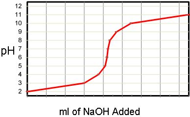
The curve above is the actual titration results of the pH Adjustment of an acid (HCl) with a beginning pH of 2.0 and an ending pH of 11.0. Dilute Sodium Hydroxide (NaOH) was used as the neutralizing agent. A brief glance at the curve indicates that the process of pH neutralization or pH adjustment is not particularly easy. In the above example 10 ml or NaOH was added to increase the pH from 2.0 to 3.0. An additional 1 ml was added to further raise the pH to 4.0, and another 0.1 ml added to raise the pH to 5.0. An increase of 1 pH unit requires 1/10th the amount of caustic required to achieve the previous increase.
Descending from 7.0 to 0.0, each unit on the pH scale represents a ten fold increase in acidity. In simple terms, very large volumes of a neutralizing agent are required to achieve very small results at high or low pH values. Yet at or near neutral incredibly small volumes must be added to achieve neutralization. This means that the pH adjustment system must be capable of delivering large volumes of reagent at extremely high levels of precision. Standard industrial methods for chemical addition and blending do not suffice.
The steep portion of the curve, which is the area near neutral (pH 7.0) is the range that most industrial effluents must be held to. In some cases,
such as de-ionized (DI) water, this curve is nearly vertical. In the case of DI water, atmospheric CO2 mixed in with only mild surface agitation is
sufficient to notably lower the pH. The point here is that the pH adjustment process is not a linear process and does not lend itself to conventional
linear control mechanisms (i.e. PID). The control system and the injection mechanism must be carefully thought through and well designed.
There are two basic system architectures in use in industry today. They are batch and continuous batch systems. A brief overview of these architectures is provided below.
pH System Architecture: Continuous vs. Batch
There are two primary system designs for pH adjustment systems: continuous and batch. There is also a third, inline, however these have no real application in industry and will be ignored here.
Digital Analysis Corp. manufacturers both continuous and batch waste neutralization systems. Generally speaking a continuous system such as those represented in our labTREAT family of wastewater neutralization systems are very well suited for relatively high flows of mildly acidic or alkaline (e.g. 2.0 < pH < 12.0) wastewaters. Compared to batching systems continuous systems tend to be smaller and less costly, however, they are also less capable.
For more demanding applications, such as those with fluctuating flows or batch discharges or those characterized by highly acidic or highly alkaline waste water then a batch system such as our pHASE or batchTREAT family of pH neutralization systems are a more appropriate choice.
In all cases we assume responsibility for the choice, size, and configuration of the system for every application.
-
Continuous flow through systems are typically used when
- Influent Flow is relatively constant and not characterized by large surges in flow.
- Influent chemistry is relatively constant and not characterized by large swings in incoming pH or chemistry
- Effluent pH limit is not overly tight (e.g. range of < 2.0 pH units
- As a single stage in a more complex application such as heavy metal reduction or fluoride removal
-
Example of wastewater effluent streams that are candidates for treatment with Continuous pH Adjustment:
- CIP Wastes from Pharmaceutical Manufacturing
- Life Science Laboratories
- University and Research Laboratories
- Semi-conductor and Nano-Technology Acid Waste Neutralization
- Heavy Metal Reduction and Fluoride Removal applications
Continuous Flow Through pH Adjustment Systems
The system depicted below is the simplest of the two basic architectures discussed here. The pH adjustment system shown here is over simplified and provided for discussion purposes. An actual system will be far more complex and detailed.
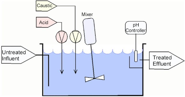
In the system shown above there is a treatment tank, mixer, acid and caustic metering pumps and a pH probe
with a controller.
The influent flow enters the tank at the bottom and exits the tank, through a distant port at the top. The objective with port
placement is to create the longest possible path between the inlet and discharge ports.
In this system the
pH treatment tank remains full at all time. Therefore one gallon entering the influent port displaces one gallon
through the discharge port. As the influent flow enters the treatment tank it is thoroughly mixed with the tank contents. If the pH
of the influent varies from the tank contents (an obvious likelihood) then the influent flow will be pH adjusted through the resultant
chemical reaction that occurs as the influent mixes with the contents. There will obviously be an equal and opposite reaction within the tank contents.
This opposite reaction is sensed by the pH probe which provides a continuous pH signal to the pH controller. The controller then paces the appropriate
metering pump to bring the body of water within the tank back into range. If the influent flow was alkaline, for example, the result would be a steady
rise in the pH of the tank contents as measured by the pH probe at the discharge port. The pH controller would then pace the acid metering pump at an
appropriate rate to bring the pH back down into range.
One of the biggest advantages to a system of this basic design is that it is simple and capable of handling relatively high flows. However, since the
tank is always full there is no guarantee, regardless of tank size or control system proficiency, that the effluent will always be in range. After all,
the pH control uses a feed-back loop, which by design does nothing until an error is sensed. If the influent flow and chemistry are high enough or strong
enough then the effluent pH can easily drift out of the prescribed bounds. Therefore pH contraventions are a distinct possibility with this system since
there is no mechanism to stop a discharge.
A batch system, however, treats a batch of a fixed volume and then discharges the batch only when it meets the discharge criteria.
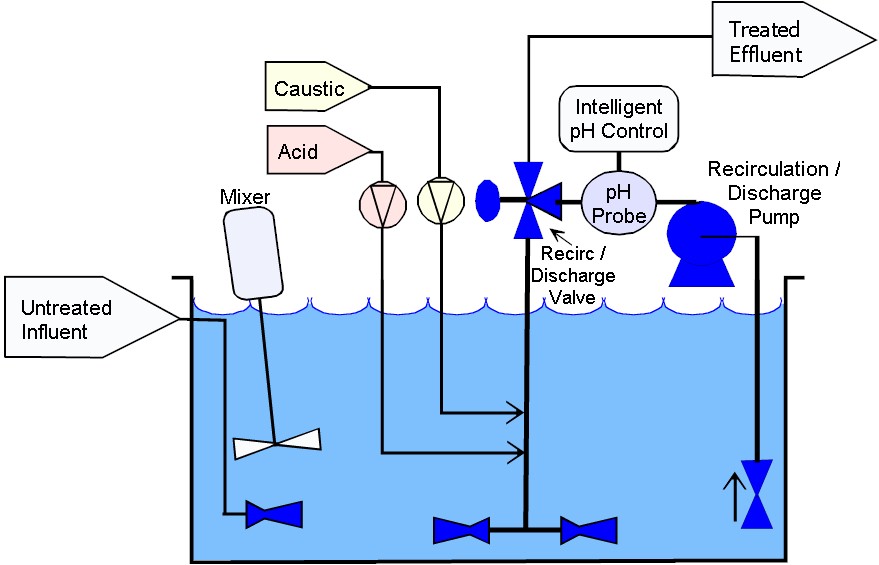
Batch pH Adjustment Systems
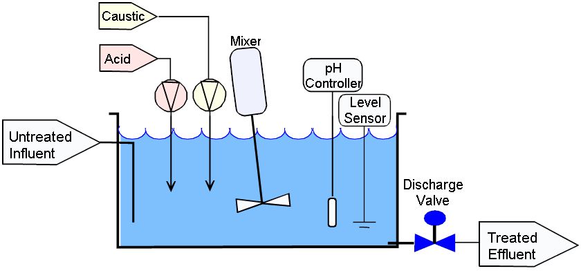
In the system shown above there is a treatment tank, mixer, acid and caustic metering pumps, a pH probe and controller, a level sensor, and a discharge valve.
The influent flow enters the tank anywhere that is convenient and exits the tank via gravity near the bottom
wherever a port can be conveniently located.
Although the Flow Through system shown above appears to be almost identical to the batch system shown here they operate in very different modes.
In this system the untreated influent fills the tank to the high level point as measured by the level sensor. Once the tank is full the pH adjustment process
begins much in the same way that the Flow Through system performed. The difference, however, is that a large batch volume is treated in one cycle.
Once the tank contents are within the acceptable discharge range, and have been for a minimum period of time the effluent Discharge Valve opens thereby
draining the tank via gravity. Once the tank is drained the cycle repeats.
The advantage of a batch system is that no effluent can flow to drain until the effluent meets the discharge criteria. No matter how large or well built
a Flow Through system may be there is no way to ensure that this is the case. Batch systems are far more suitable for effluents that may be characterized
by large swings in influent pH, concentrated discharges, or large swings in flow rate. The majority of the systems that we install are batch systems since
they are inherently safer and capable of handling streams of any composition.
It is important to reiterate that the systems shown here are simplified versions of the systems that we design and build for industry.
There are many more considerations that are incorporated into system design. We have developed a technology referred to as system "Optimization" that
involves very specific criteria for tank size and geometry, chemical injection methods, probe installation and location requirements, and most importantly,
control algorithms. A separate technical article on "Optimization" is available upon request. All of our systems, whether they be Flow Through
or Batch employ system "Optimization" technology.
"Optimized" Batch pH Adjustment Systems
The throughput of a conventionally designed pH neutralization / adjustment system is limited by several major short comings.
These short comings pertain to pH probe response time, mixing efficiency, tank design, chemical metering precision, chemical reaction times,
and pH control intelligence. "Optimized" pH control technology addresses each of these weak areas individually and synergistically.
With the implementation of "Optimized" pH control we are able to achieve system throughputs that simply are not possible with conventionally designed systems.
All of our pH adjustment systems employ this technology. A technical paper describing "Optimization" in detail is available upon request.